 At Fair Cape Dairies, their commitment to environmental stewardship is at the heart of everything they do. As pioneers in the African dairy industry, they take immense pride in their innovative efforts to reduce their carbon footprint and enhance sustainability across their operations.
Leading the Way in Carbon Footprint Transparency In a groundbreaking move, Fair Cape Dairies became the first dairy company in Africa to publish their carbon footprint on their milk bottles. This initiative reflects their dedication to transparency and their ongoing efforts to educate consumers about the environmental impact of their choices. By clearly displaying their carbon footprint, they empower their customers to make informed decisions and contribute to a more sustainable future. Eco-Friendly Packaging Innovations In 2019, they took another significant step towards sustainability by changing their Fair Cape EcoFresh milk bottle from white PET to clear PET. This change not only improves the recyclability of their bottles but also aligns with their broader goal of reducing plastic waste and promoting a circular economy. Clear PET bottles are easier to recycle, ensuring that more plastic can be reused and repurposed, thereby reducing their overall environmental impact. Harnessing the Power of Renewable Energy Since October 2018, Fair Cape Dairies has been generating renewable energy at their milking parlour, significantly reducing their reliance on fossil fuels. Their latest project focuses on utilizing solar energy, a clean and inexhaustible resource, to power their daily operations. The sun, rising unfailingly each morning, provides a sustainable energy source that does not deplete natural resources or produce harmful emissions. Their solar energy system now supplies 26% of the daily energy demand at their milking facility, enabling them to milk their cows using renewable energy during daylight hours. This initiative has led to an average reduction in CO2 emissions by 12.2% per month, showcasing their commitment to decreasing their environmental footprint. Enhancing Animal Welfare At Fair Cape Dairies, the well-being of their cows is paramount. They have constructed technologically advanced sheds designed to offer optimal comfort and space for each cow. These sheds feature both undercover and open-air sections, with innovative ventilation systems that channel hot air out and allow cooling breezes to flow through. This environment not only ensures the health and comfort of their cows but also contributes to their overall welfare. Their Animal Welfare programme is dedicated to maintaining high standards of health and comfort for their cows. By focusing on the well-being of their livestock, they ensure that their dairy products are of the highest quality, produced in a manner that respects both the animals and the environment. A Greener Future Fair Cape Dairies' commitment to sustainability is unwavering. Through innovative practices and forward-thinking initiatives, they strive to minimize their environmental impact and lead the dairy industry towards a greener future. By reducing their reliance on fossil fuels, embracing renewable energy, and enhancing animal welfare, they are not only safeguarding the planet but also setting a positive example for others to follow. Join them on their journey to sustainability. Together, we can make a difference and ensure a healthier, greener world for future generations.
0 Comments
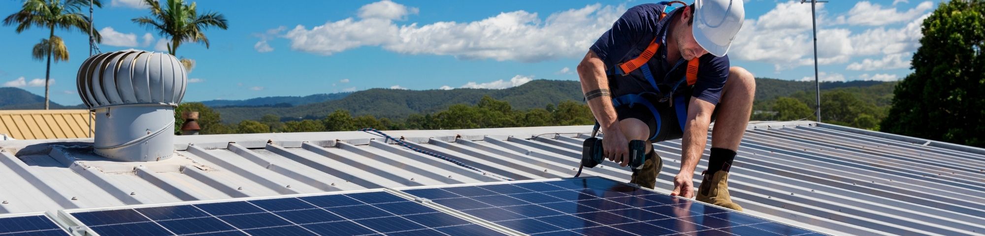 You've contacted us for a quote, now you are happy and ready to proceed with installation and leave your loadshedding fears in the past but hold on there is a few things you need to do first.
You are required to apply for authorisation from the City of Cape Town if you intend installing an embedded generation (EG) system such as a rooftop solar PV. This is known as a small-scale embedded generation (SSEG) application for systems with a generation capacity smaller than 1 mega-volt ampere (MVA). There is no charge to register EG systems with the city, however some fees may apply to acquire the relevant documentation. A fine will be applied if you fail to register your system. If you are in Eskom's area of supply, you need to apply to Eskom for consent to connect the EG to the electrical grid. To apply for SSEG authorisation you need to complete the application for Connection of Embedded Generation form. The form requires technical information that your installer, like us, will be able to assist you with. The City will assess your registration for authorisation . This may include a visit to your property to confirm that your meter and connection are able to support the EG. If you have a wheel meter this first needs to change to a prepaid meter which will be done at the cost of the City. Once all relevant information has been provided, the city will issue a Permission to Install Letter, allowing you to install your proposed EG system. You cannot install any PV generating equipment until you have received this letter. After you have installed and tested your EG, you will need to submit the following documents to the City: Grid-tied systems: · Grid-tied SSEG Installation Commissioning Report completed and signed by an Engineering Council of South Africa (ECSA) registered electrical engineering professional. · Final copy of the circuit diagram. · An electrical installation Certificate of Compliance. · Signed Supplemental Contract for Embedded Generation. A Commissioning Approval Letter will then be issued within 10 working days. Off-grid / standby systems: · Electrical installation Certificate of Compliance A Commissioning Approval Letter will then be issued within 10 working days. You can find more information on the City of Cape Towns website. 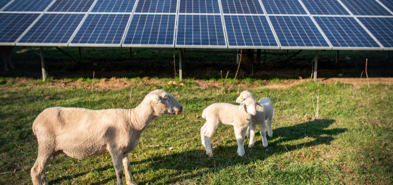 The sun provides a tremendous resource for generating clean and sustainable electricity without toxic pollution or global warming emissions however it does have some potential environmental impacts like land use and habitat loss. Most ground-mount solar projects are built are on gravel, turf or dirt however mounting solar on gravel, dirt or turf can ruin the natural ecosystem. When solar was first starting, many engineers didn’t think about the environmental impact of solar farms with regards to pollinators like birds, bees and butterflies. Now, businesses, cities and farmers are trying to do better especially now that we know the importance of pollinators to our food supply chain and everyday life. Dual-use solar, also known as agrivoltaics, is the combined production of photovoltaic power and agriculture on the same area. The coexistence of solar panels and crops involves light sharing by spacing out the panels and/or elevating them on 1.8m – 2.4m poles above the crop to generate shade and create a kind of microclimate over the growing area. This can provide clean power that preserves beautiful landscapes and ecosystems that are in danger from coal mines, oil wells and fracking. The height and spacing of the poles and panels vary based on the crops, livestock and equipment that will be used in the field. Some crops that can benefit from this system are blueberries, tomatoes, squash and leafy greens as the shade created by the panels cuts down the heat stress of the plants this, in turn, can produce a larger crop size and yield. The panels have also been effective in protecting grapes from hale as well as reducing evaporation and thus saving water. When it comes to livestock, sheep have received the most attention for grazing solar fields as they pose the least risk of damaging the panels. Agrivoltics could be a great investment to farmers as it provides another source of income especially in times of drought when farming might take a hit. It is beneficial for us as a country as it can help with our ever-struggling power supply, this system could also assist in creating jobs for some of the 34.9% of unemployed South Africans. This system has successfully been used in countries like the US, UK and Germany. AuthorNatashja van der Merwe Sources include
ucsusa.org dw.com energymonitor.ai lancasterfarming.com energyindustryreview.com  Compiled by Sune DiedericksWith the rising issues revolving Eskom and our planet burning out due to global warming (a topic for another day), it’s difficult to ignore the fact that we have to start looking at other alternatives for energy. Solar panels are not only synonymous with households and commercial use, but we can also start focusing on “going green” with our education, health and transport sectors. |
 |
|
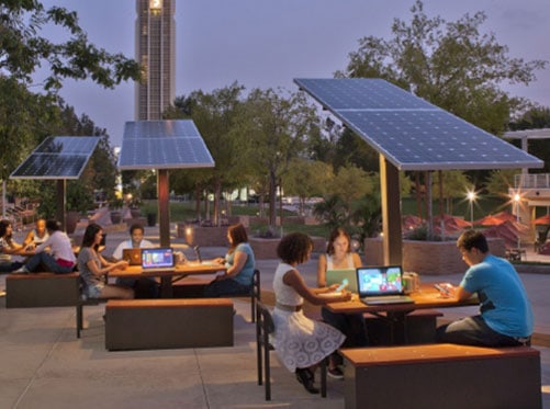
Solar power can have an educational benefit.
Students can get first-hand experience of solar energy and how it is used. From learning about energy, the sun, financial saving to how different tilts are used, there are many ways of using solar as an educational tool. But solar does not only benefit on an educational level, it can also shape the minds for our leaders of tomorrow. Solar power in our schools can create awareness and model the young minds to become eco-minded and ensuring our future is green.
Improving our environment.
The study conducted by the Environmental Research Letters, states that solar energy in our schools can reduce the education sector’s carbon footprint by up to 28%.
Environmental, financial, educational, and so much more advantages are linked to solar energy. With our economy that is taking a dip, to our lights being switched off, we need to start focusing on how to ensure that our children will not be influenced by these factors. By teaching them about solar energy from an early age and introducing them to these solutions we can ensure a brighter future.
Sources Consulted:
https://gosunbolt.com/solar-benefits-for-schools/
https://www.conserve-energy-future.com/benefits-of-solar-panels-for-schools-and-universities.php
https://news.energysage.com/solar-panels-for-schools-how-k-12s-and-universities-can-benefit-from-solar/
https://news.stanford.edu/2019/05/02/happens-schools-go-solar
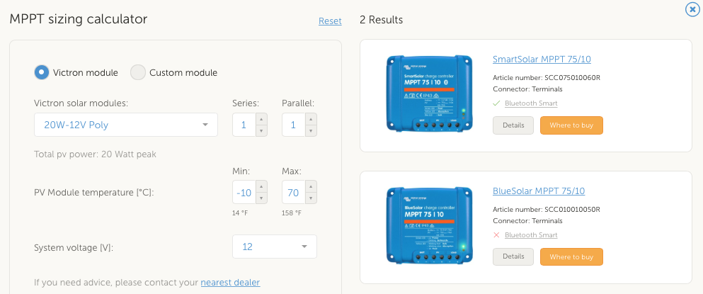
We stock a wide range of both MPPT & PWM solar charge controllers. See the BlueSolar and SmartSolar Charge Controller MPPT - Overview. In the MPPT model names, e.g.. MPPT 75/50, the first number is the max. PV open circuit voltage. The second number, 50, is the max. charge current. Use the MPPT Excel sheet or Online MPPT Calculator for PV sizing calculations.
For more info about PWM or MPPT charge controllers, read Victron's whitepaper: which solar charge controller: PWM or MPPT?
For more information on each solar charge controller, visit our products page or the Victron Energy site.
For more info about PWM or MPPT charge controllers, read Victron's whitepaper: which solar charge controller: PWM or MPPT?
For more information on each solar charge controller, visit our products page or the Victron Energy site.
MPPT Sizing Calculator